Measuring inner diameters
Accurately checking the dimensional tolerances of bores ensures their proper fit (clearance and interference) when assembled with a mechanical shaft.

Why controlling inner diameters?
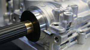
The main purpose of inner diameters checks is to verify that the bore of a machined part will fulfill its main function: to fit correctly with a shaft.
Depending on the application, this assembly may have a clearance (the shaft, with a smaller diameter than the bore, may slide in the bore, as in the case of an engine piston in its liner) or a certain level of tightness (the shaft, with a larger diameter than the bore, is then solidly attached to the bore after assembly, as in the case of a gear on an engine shaft).
Very simple tools such as calipers, bore gauges or internal micrometers may be used, but they do not have the precision, the level of traceability or the automation required by many industries.
The control of borehole diameters by the pneumatic method
Pneumatic comparators are widely used in manufacturing and quality control processes to verify the inner diameters of manufactured parts.
The method employs the technology of air plug gauges. These gauges use compressed air to measure the inner diameter of a hole or bore. The gauge consists of a hollow cylinder with at least two small orifices at its end. It is inserted into the hole or bore to be measured.
Compressed air is continuously introduced into the cylinder and exits through the orifices. The pressure of this air flow varies according to the spacing between the ports and the edges of the bore being tested. The resulting pressure is measured to determine the internal dimensions of the hole or bore.
More precisely, the difference between this pressure and the pressure of the upstream compressed air is measured by a device called a pneumatic flow meter, measuring column or pneumatic comparator. It represents this pressure difference by a liquid height or by its graphic display on software. This height of liquid is compared to that obtained for standard parts of desired diameters.
Pneumatic gauges offer several advantages over other types of measuring tools for checking inner diameters, including high accuracy, non-contact measurement and the ability to measure complex shapes and geometries.
They are commonly used in industries such as automotive, aerospace, defense, and medical devices to ensure precision and accuracy in the production of components such as piston liners, bearings, gun barrels, syringe barrels, etc.
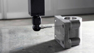
Inner diameters control using touch probes
Touch probe technology can be used to measure inner diameters of parts, and in particular linear displacement (LVDT), touch trigger, or scanning probes. These sensors are held by a machine and placed near the part to be inspected. The machine controls their position in space. They are moved until a contact with the surface of the part to be checked is detected. The coordinates of the contact points are then recorded.
These coordinates are compared to calculate the controlled inner diameter. Depending on the technology used, the probes measure either two fixed points or a series of points along the bore.
However, due to the size of these probes, these technologies are mostly suitable for relatively large bores. In addition, the principle of touch probe measurement reserves them for parts whose surface is not likely to be damaged by contact with the probe.
Manual, automated, analog or digital control?
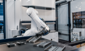
If the pneumatic method is traditionally manual, it can, like the tactile methods, use automation and robots to pick up parts, move probes or gauges, and even sort parts according to their conformity or not. These automated systems are fully adaptable to the user’s part types and measurement rate requirements. They are generally designed, assembled and programmed by the supplier.
In addition, software can be used to record measurement results or diameter comparisons. In the case of touch probe measurement, software can reconstruct a digital image from the measured coordinates. The desired diameters can then be determined on this digital image by an algorithm or by the user via an image processing function of the software.
Generally, software offers very interesting functions for the user: programming of inspection procedures, display of simple diameter measurement results for quick decision making, statistical calculations of result series, automatic generation of measurement reports.
Thanks to the recording of measurement data and the management of administrator or user accounts, they also offer a level of traceability that is not possible with analog systems.
ASSOCIATED SETSMART TECHNOLOGIES
Visit the technology pages for more information on the control techniques used